Harris/Gates Stereo 80 Broadcast Console

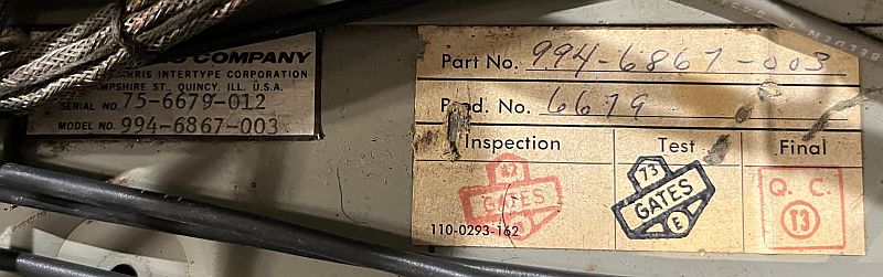
This page describes a mid-1970's transistorized Harris/Gates Stereo Broadcast Console. The console was manufactured by the Gates Division of Harris-lntertype Corporation
and bears the Model Number 994-6867. The model number includes the Stereo 80 eight-channel stereo console, complete with six preamplifiers, five boosters, five program/monitor/cue
output modules (interchangeable), and one power supply panel. It sold for $3,995.00.
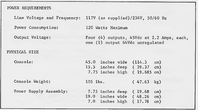
The console is 45 inches wide, 15.5 inches deep, and 7.75 inches high. The console is heavy, weighing 105 pounds. The power supply is designed for mounting in a 19-inch rack.
The power supply is 19 inches wide, 7.75 inches deep, and 7 inches high.
Below is a picture of the model number/serial number and inspection tags inside the console.
The Gates Stereo 80 console was designed for the FM stereo broadcaster and provides flexibility with good audio quality. The console has
eight mixing channels and features a wide choice of inputs and outstanding performance specifications such as: frequency response from 20 to 20,000 Hz
with less than 1-dB variation and distortion less than 0.5% across that frequency range. The console has eighteen inputs that may be switched into eight stereo mixing
channels to provide a degree of flexibility that will satisfy virtually any stereo requirement. Inputs include five microphones, four turntables,
five tapes (cartridge or reel-to-reel), three remotes, and one network.
The left-hand side of the console is shown below.

Mixing Channels 1 and 2 are equipped with low-noise preamplifiers, and are designed to be used with low impedance, broadcast-type microphones.
Each of these stereo channels may select from two different pairs of stereo input signals by means of a front-panel switch.
Channel 3 is also equipped with low-noise preamplifiers, and is also intended for use with low-impedance, broadcast-type microphones.
This channel has a stereo input (two microphones) and is assigned to the control room because these microphones function as part of the talkback system.
The console has a label added by the former user above the Channel 3 attenuator control that reads "D.J. MIKE."
The right-hand side of the console is shown below.
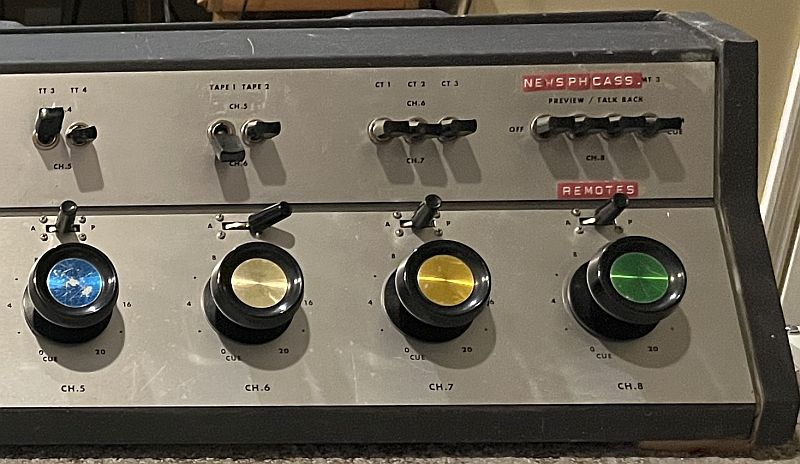
Channel 4 (on the left-hand side), and Channels 5, 6, and 7 (on the right-hand side) are all medium-level inputs and may be used with stereo turntable
preamplifiers, reel-to-reel tape, or cartridge machines. All channels have input transformers whose center tap may or may not be grounded,
depending upon the given installation. They are shipped with the center taps ungrounded. A nominal level of -20 dBm or +4 dBm at 600 ohms is required.
Input pads for the +4 dBm are factory-provided on the various tape inputs (two tape and three cartridge inputs). The four turntable inputs have -20 dBm level inputs.
Channel 8 is specifically designed to function with network and remote lines as sources. Various combinations of preview, talkback, and program
cue are possible using the front panel switches. A nominal input of at least - 20 dBm at 600 ohms is required for remotes and - 14 dBm for the network.
The three remote inputs are stereo and the one network is monophonic. The console has labels added by the former user above the Network and three Remote switches that read "NEWS, PH, and CASS.,"
presumably referring to a news network feed, landline telephone, and cassettes.
All eight channels may be switched to either the program or audition positions to permit independent monitoring of any of the incoming sources
without disturbing on-air programming.
Channels 4 through 8 have a cue position associated with the channel attenuator that provides signal to the amplified cue system.
This signal can be monitored by an internal console speaker or external headphones. On Channels 1 and 2, the center position of the program audition
key switch provides a microphone cue signal to the cue selector switch. On Channel 3, this position is used with the control room microphones for talkback.
The center of the console is shown below.

Two VU meters indicate the volume levels of the Program Left and Right Channels. Below the meters are controls for adjusting the volume of the Control Room speakers and the
volume of the CUE speaker in the console. The red-colored switches switch the monitor channels/speaker to monitor the Audition, Program, or External sources and to switch
the CUE speaker to monitor the Mic 1, Mic 2, or CUE bus channels. This console has been modified to add a toggle switch and dual volume control adjacent to the CUE switch for an
unknown purpose.
A protective system of warning lights and relay speaker muting is provided to prevent acoustic feedback and broadcasting of cue signal when "live" microphones are nearby.
The swing-up transformer deck containing the muting relays and relay driver board is shown below.

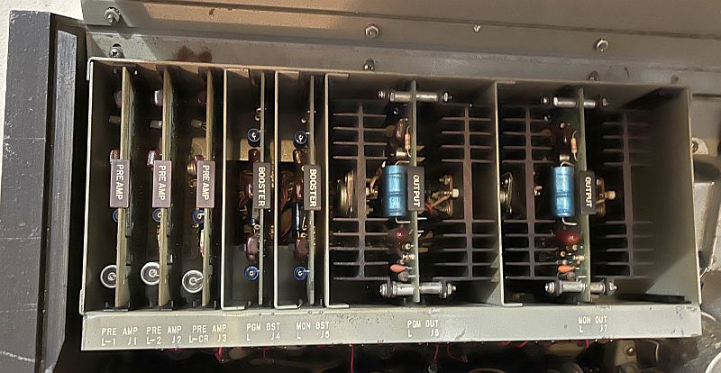
Each solid-state plug-in amplifier is mounted on a separate printed circuit board, which in turn mounts in a card-rack holder.
These modules include: six preamplifier modules, five booster amplifier modules, and five output amplifier modules. The left-hand and right-hand circuit card cages are
shown below. As seen in the second picture below, PreAmp R-1 J8 is missing.
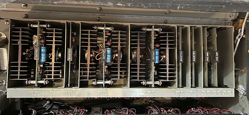
The circuit card cage layout shown below.

Silicon transistors are used to assure meeting performance specifications and assure optimum console operation over a wide ambient temperature range.
All amplifiers are completely accessible when the top of the console is opened, simplifying maintenance.
Program, cueing and monitor amplifiers all have the same electrical design and construction, and are completely interchangeable. As a result, two backup
program amplifiers are provided as part of the console.
Below is a picture of the bottom of the console. Connections to the console are made throught the various holes in the bottom of the console.

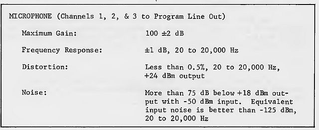
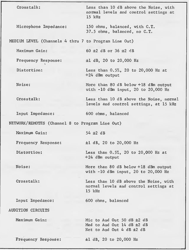
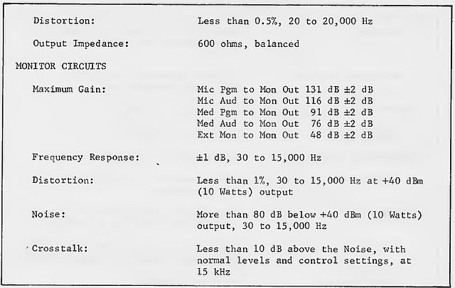
Below are specifications for this console.
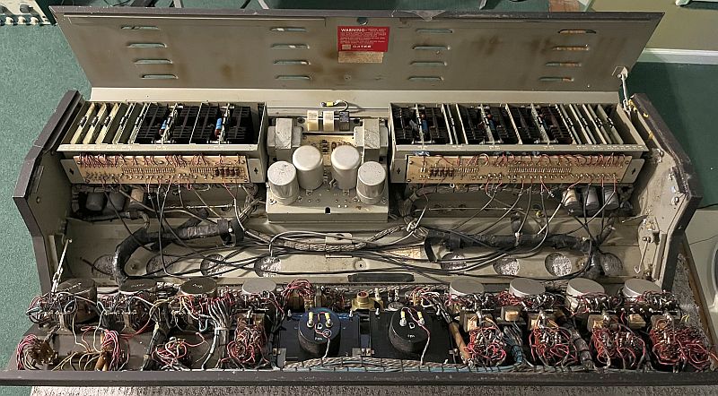
The picture below shows the console with the top open and the front panel open and folded forward. This arrangement allows easy access for maintenance and adding
connections for external audio sources.
The console was is good shape when I received it. Initial inspection showed that PreAmp R-1 J8 (Item 20 in the picture above) was missing. This preamp is for the
CH1 Right Microphone A input. I replaced it with one I purchased on eBay. The purchased preamp had been modified to jumper several of the card edge connectors that
bypassed the transformer input. In addition, a resistor was taken out of the circuit. I removed the jumpers and placed the resistor back into the circuit. The purchased
circuit card now works as designed.
The console has also been modified to include a ganged/dual potentiometer and toggle switch on the front panel next to the CUE input selector switch. This modification is shown below.
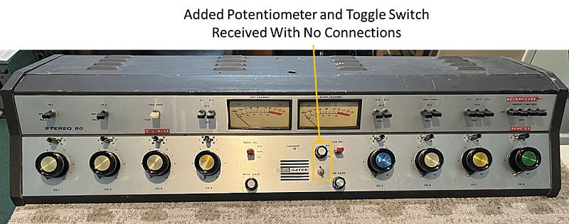
At one time there were connections to the potentiometer and toggle switch, but those connections had been removed when I received the console. The potentiometer and
toggle switch internal to the console are shown in the picture below.

The potentiometer for the CUE speaker volume is shown on the right in the picture above. That potentiometer is designed to be 10k-ohms but it had been replaced with a
5k-ohm potentiometer. I replaced the potentiometer with the correct value. There is a 1k-ohm resistor in series with the source signal to the potentiometer. One electrical
schematic I found on line listed that resistor as 10k-ohm but a later electrical schematic I found on line listed that resistor as 1k-ohm. The manufacturer apparently modified the
circuit in later models to reduce the resistor to 1k-ohm.
Further inspection revealed that several inputs have been wired in parallel making it a function as a monophonic console for those inputs. The inputs include:
- CR Mic Left wired to CR Mic Right
- TT2 Left wired to TT2 Right
- CT1 Left wired to CT1 Right; - input cable wired to CT1 Right
- CT2 Left wired to CT2 Right
- CT3 Left wired to CT3 Right
- RMT1 Left wired to RMT1 Right
- RMT3 Left wired to RMT3 Right
- Mic A Right pins 1 and 3 (Channel 1) - input cable connected (no preamp)
- Mic A Right pins 9 and 11 (Channel 2) - input cable connected
These parallel connections were easy to remove to make those inputs stereophonic.
Other observations include:
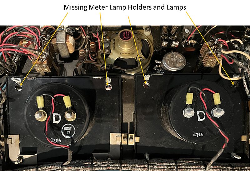
- VU meters are not illuminated. The 4 bulbs and their bayonet mounts have been removed and the black and brown wires to the bulb mounts have been tied off
- CT1 produces right and left outputs through Channel 6
- TP1 does not play properly through Channel 5. One channel (left or right has no output using a signal generator)
- TP1 does play properly through Channel 6
- No output from TT1 or TT2 right channel when switched to CH5; output is proper when switched to CH4 - both left and right outputs
- CUE produces no sound output when switched to BUS; significant hum is produced through the CUE speaker on the front panel
- Console is wired such that CH1, CH2 mute the CR speakers along with CH3 muting the CR speakers
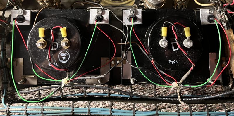
The picture below shows that the four lamp holders and lamps are missing.
I replaced the missing lamp holders and lamps with white light emitting diode (LED) lamps. I made four small aluminum plates with grommets to mount
the LED lamps. The threaded posts next to the holes in the meters was intended to mount the original lamp holders that used incadescent lamps. I used
those posts to mount the small aluminum plates. The black and brown wires supply 64 Volts dc to the lamps. The original incadescent lamps were apparently 32-Volt
lamps as the two lamps for a single meter were originally wired in series. I used 28-Volt LED lamps wired in series with a 680-ohm resistor in series with the lamps
to accommodate the 64-Volt dc supply. The picture below shows the new LED lamps installed in the console.
The console is designed such that turntables TT1 and TT2 can play through CH4 or CH5, selected by the switch above the CH4 attenuator.
Likewise, turnables TT3 and TT4 are designed to play through either CH5 or CH4, selected by the switch above the CH5 attenuator.
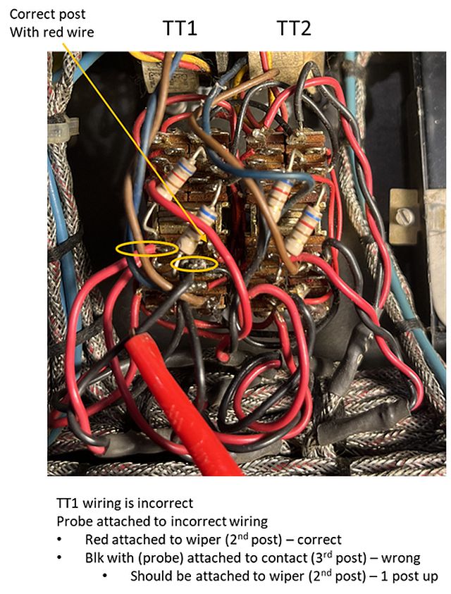
Addressing why turntables TT1 and TT2 do not properly play (right channel missing) when switched to CH5 required significant schematic analysis, continuity measurements,and
comparison to the other channels that work. I eventually determined that sometime in the past a wire to the TT1 switch had most likely broken and someone resoldered it to the
incorrect connection post. The connection posts on the switch are numerous and close together and therefore making such a mistake is understandable. The picture below shows the
incorrect wiring as received.
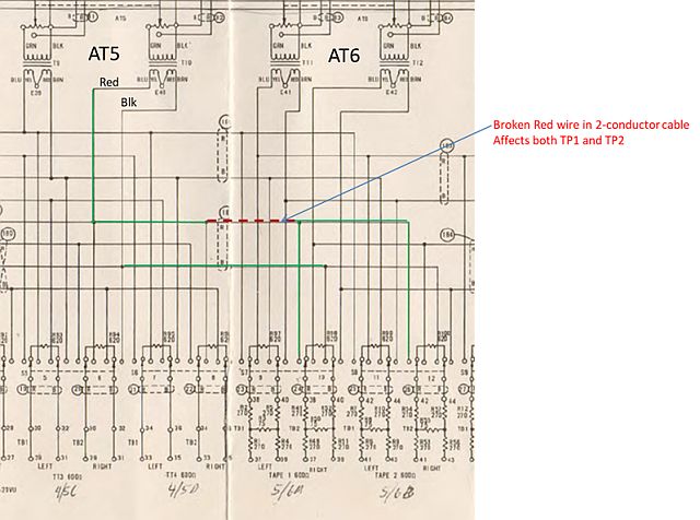
I corrected the error, but the failure still persisted. Further measurements resulted in no continunity between the right channel TT1/TT2 CH4 and TT4 CH5. Apparently a black wire
in a two-conductor cable had broken. I ran a new wire between the two points and the console now works as intended and both play properly through CH4 and CH5. The picture below
shows the broken connection in the electrical schematic.
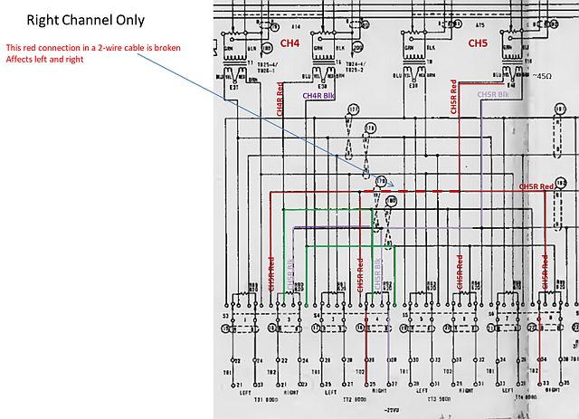
A similar problem was discovered with Tape 1 and Tape 2(TP1, TP2). TP1 or TP2 plays correctly through CH6; however, the right channel was missing when playing through CH5.
Measurements indicated a broken red wire in two-conductor cable. The picture below shows the broken connection in the electrical schematic.
Investigation into the CUE circuit revealed a shorted MSP-U45 Darlington pair transistor on the CUE Audio Booster circuit card. The transistor had a short from
collector to emitter found by resistance measurements across the transistor. The CUE circuit works properly now. There is not a lot of gain the the CUE circuit; signal levels
need to be near 0-dB on the VU meters with the associated channel attenuator set at "12" in order for the CUE sound to be comfortably heard through the front-panel CUE speaker
when the channel attenuator is placed in the CUE position.
As noted above, the console as received had been modified such that CH1 and CH2 mute the CR speakers along with CH3 muting the CR speakers. Inspection showed that the
wiring at TB15 had been modified to make CH1, CH2, and CH3 mute the control room (CR) speakers when these channels are in the Program position. I left this modification as is.
External audio inputs to the console are made at a long terminal board mounted to the front side of the left and right channel card cages. The left and right channel terminal boards are
shown below.


The terminal numbers for the input connections are listed below.
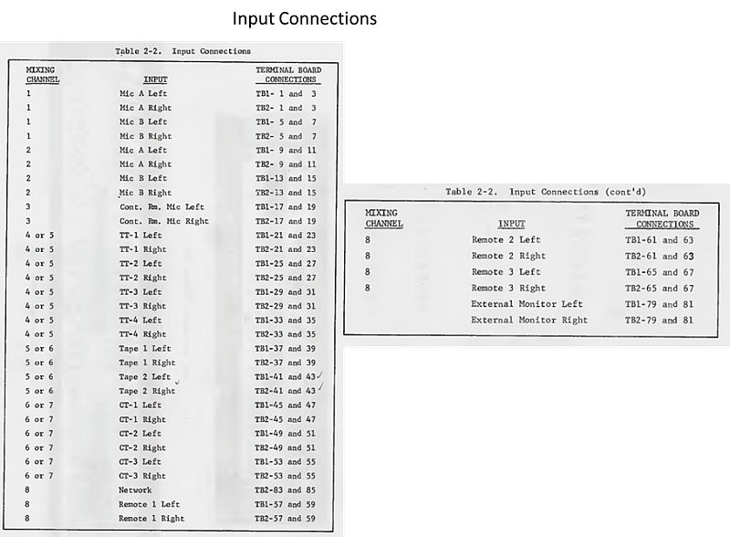
The Left and Right Channel Program Outputs are availabe on terminals 69 and 71 and are 600-ohms balanced and produce +8dBm output when the VU meters read 0 VU.
This level is rather large and typicaly would be attenuated to drive the transmitter. Left and Right Program headphone high impedance balanced outputs are
available on terminals 75 and 76. Left and Right Audition Outputs are availabe on terminals 95 and 97 and are 600-ohms balanced and produce -26 dBm output
when the VU meters read 0 VU. A CUE headphone jack connection is availble on terminals 89, 91, and 93 of the Right Channel terminal board (TB2).
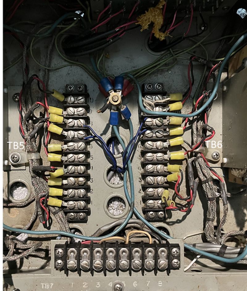
The connections for the monitor speakers are located on TB5 (Left) and TB6 (Right), underneath the swing-up transformer deck that is located between
the two card guide assemblies. Terminals 1 and 2 are for the lobby speakers which are not muted. Terminals 3 and 4 are for the Studio A speakers,
terminals 5 and 6 are for the Studio B speakers, and terminals 7 and 8 are for the Control Room speakers. These three locations are all muted.
The connections for the warning lights are on TB7, located underneath the swing-up transformer deck. Terminals 1 and 2 on TB7 are for the 117 V AC
used to energize the warning lights. Terminals 7 and 8, on TB7, are for Studio A, terminals 5 and 6 are for Studio B and terminals 3 and 4 are
for the Control Room.
The above connections underneath the swing-up transformer deck are shown below. The blue wires in the center of the picture are for the Control Room speakers.
The separate power supply is interconnected to the console with eleven twisted-pair cables, with a total of 22 connections. The console and the power supply have
a 27-pin terminal board to make the dc power connections. Pin 1 on the power supply is connected to Pin 1 in the console. The other 21 connections are similarly connected
pin-to-pin between the power supply and console. The picture below shows the terminal board inside the console.
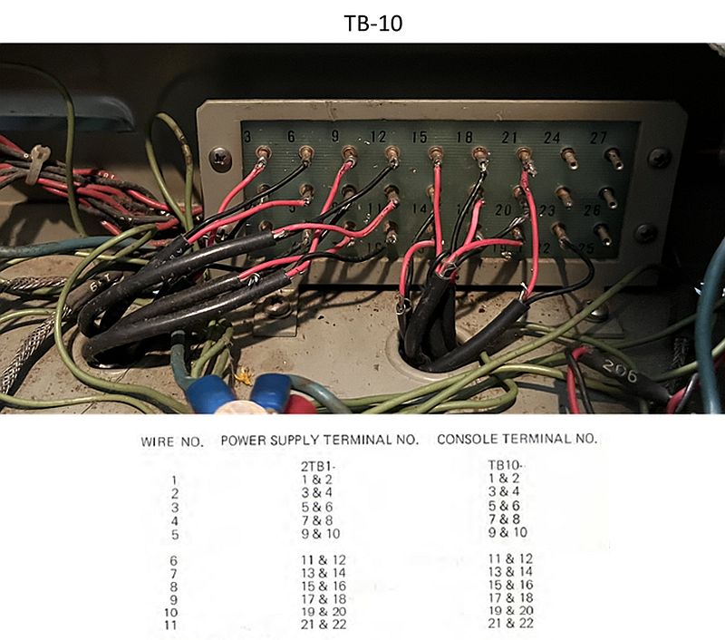
Pairing of the connections is shown in the table in the picture above. For example, connections to pins 1 and 2 are in the same cable and connections to 3 and 4 are in the same cable. Similar
pairing is maintained for all 22 connections in the 11 twisted pair power supply cables.
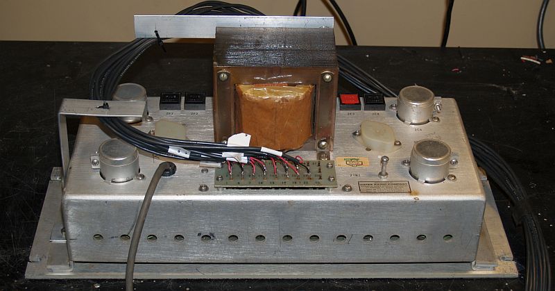
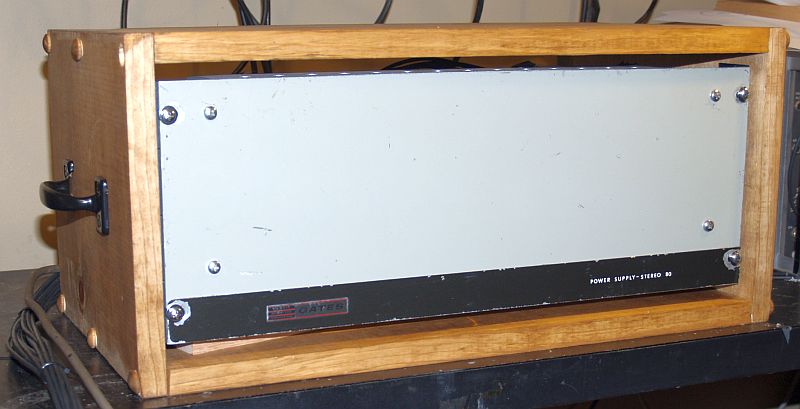
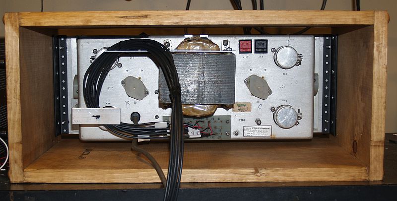
The power supply assembly for the console is a separate assembly and is designed for 19-inch rack mounting. Pictures of the power supply are shown below.

The power supply assembly contains a power transformer and four regulated dc power supplies. These four power supplies are designated LM (Left Monitor), RM (Right Monitor), LP (Left Program),
and RP ( Right Program).
Below are specifications for the power supply assembly.
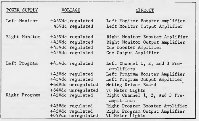
Below is an electrical schematic for the power supply with its outputs labeled.
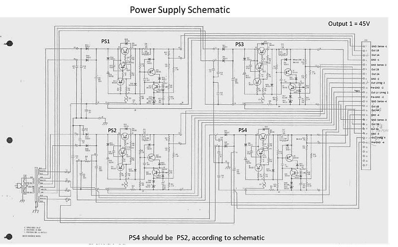
Each power supply has a connection for +dc output, dc ground, +sense, - (ground) sense. Two of the power supplies have a +dc unregulated output and grounds to power the VU meter lamps.
One power supply has an unregulated output and ground for the muting driver board.
When I received the console and power supply, the 22 interconnections were made with eleven shielded twisted-pair cables that were permanetly interconnected and the console and power supply had to be
moved and as interconnected assemblies. I cut the cables at the power supply and labeled each cable. The cables were wired such that the red lead was always connected to the lower number of a pair
and the black lead connected to the higher number of a pair. This arrangement helped prevent mistakes in connecting the power supply to the console.
The eleven power supply cables were quite long - over 25 feet. I cut the cables and removed approximately 6 feet and added 24-pin Cinch-Jones plugs such that the console and power supply
could be separated for transport. The Cinch-Jones plugs are shown below.
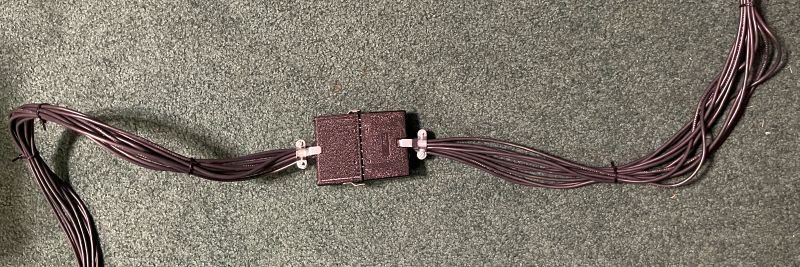
The power supply contains no strain relief for the cables. As such, the cables are held in place by only the solder connections to the terminal board. I added two aluminum brackets to add
strain relief to the cables. The two brackets with the cables tied to them are shown below.
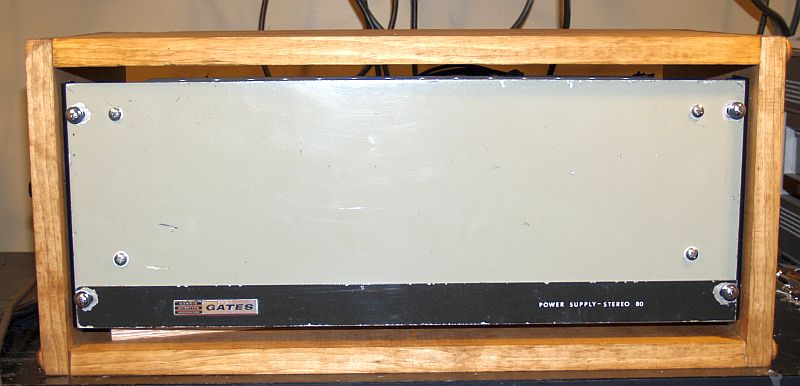
I built a wooden box to contain the power supply. A 7-inch long (4U) rack rail mounted inside the box holds the power supply securely inside the box. Aproximately 1/2-inch clearance above
and below the power supply facilitate air flow. There is no back on the rear of the box. Handles on both sides of the box facilitate handling. The power supply and box are shown below.
I used and modified some of the original audio source connections, and added connections, to connect to several audio sources to include:
1) Control Room (CR) stereo microphones. I purchased a microphone desk stand (Gator Frameworks Compact Desk Stand - GFW-MIC-0600), a Gator Frameworks Stereo Microphone Bar Mount - GFW-MIC1T02,
and a Gator Frameworks Microphone Clips - GFW-MIC-CLIPW. I used the microphones supplied with my Sony TC-630 tape recorder.
2) One turntable is connected to TT1. The turntable is my QRK Model 12C turntable with Micro Trak Model 303 Stereophonic Professional Transcription Tonearm.
An Audiometrics preamplifier, Model PA-1, provides the turntable RIAA de-emphaisis and amplifies the audio level to that required by the console.
3) One cassette deck is connected to TT3. I may add a Multicomp PRO Model 50-14820 Line Level Amplifier to increase the level to produce adequate volume for CUE circuit.
4) A computer audio output is connected to TP1. A computer line amplifier, Model LGB-1, operating at maximum gain provides sufficient gain to drive the console. I may add a
Multicomp PRO Model 50-14820 Line Level Amplifier to increase level to produce adequate volume for CUE circuit.
5) I added cables and connectors for stereo headphones connected to Program Headphone outputs. I used an MCM Model 50-14818 Stereo Headphone Amplifier to drive Koss Model 4/AA headphones that were
popular in the mid 1970s.
6) The Cart Player 1 (CT1) is already parallel-wired for monophonic operation and has one lead (Left and Right) external to console. I left that connection as received.
7) The Program outputs have more than sufficient level to drive a transmitter exciter or other end-points. A two-channel variable attenuator is required to reduce the Program output level.
A variable attenuator such as the RDL Model STP-1 Stick-On Dual Variable Attenuator works well. The attenuator is small such that I mounted it inside the console on a bracket that I made.
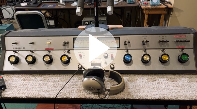
The picture below shows the console in a potential "broadcast configuration."

Click on the image below to see a video of the console playing "The Lion Sleeps Tonight" by the Tokens.